Welcome

DIY Off-Grid Power Equipment

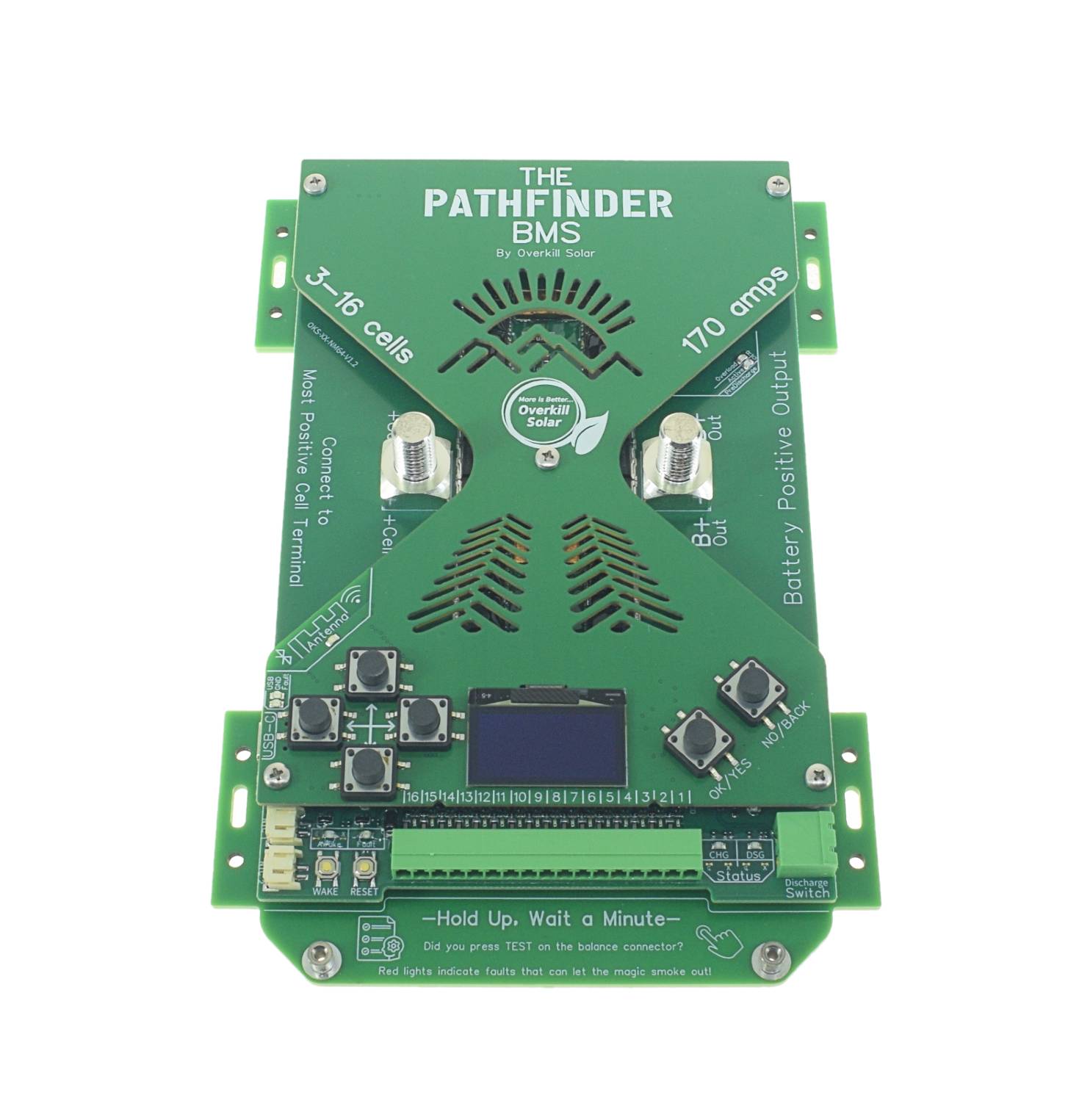
Pathfinder BMS available now!

Categories

View more product categories

Recent Products

Recent Posts

Posted on Leave a comment

Measuring State-of-Charge is difficult

Measuring the state of charge of a lithium battery is difficult. Very difficult. In fact its practically impossible to just measure SOC of a lithium battery, it must be calculated from a known starting point, by continuously monitoring and integrating the charge (coulombs) in and out of the battery.

One cheap way to estimate SOC is to compare the battery voltage to a predetermined Volts-to-SOC lookup table. This is how the old JBD BMSs are gauging SOC, and it’s a rough estimate at best. It works for lead-acid batteries, but Lithium batteries have a very wide, flat region on their volts-SOC graph that means there is a lot of uncertainty when comparing voltage to state of charge.

Early in the design process for The Pathfinder BMS, I was planning on programming the User Interface controller to track State of Charge (SOC). We did some research, and my programmer told me this was going to be too complicated and take forever, so we should just buy one of the chips that are made to track battery SOC. It will just work!

I picked the Texas Instruments BQ34Z100 “fuel gauge” chip for the job. (The main BMS functions are handled by the Texas Instruments BQ76952)

TI agrees with my programmer:

A gauging algorithm with a high level of accuracy is quite complex and often requires a large amount of software development. Therefore, a stack-level gauge like the BQ34Z100-G1 can be used in unison to provide State-of-Charge and State-of-Health.

Texas Instruments application note: Battery Gauging Algorithm Comparison

This chip has given me nothing but trouble. It requires a complicated learning cycle that is supposed to be completed by an engineer and then the resulting firmware image is to be copied to identical battery packs on the production line.

We set out to build the best BMS for DIY installation, which means each installation is different, and this is making it very difficult to complete the learning cycle in the field.

Selectable SOC algorithms

To fix this situation, I’ve gone back to the drawing board and programmed a simple, basic SOC tracking algo.

It’s called “BasicSOC”

This SOC tracking algorithm uses a simple method of resetting the capacity at high and low voltage points and tracking coulombs in between the reset points.

As of firmware update V_0.301, the user can select which SOC algo is used to report SOC on the app(s) and OLED. See the updated datasheet: Pathfinder BMS datasheet PDF

This method suffers from drift if the battery experiences shallow cycles or long periods of low activity, but maintains good accuracy if the battery routinely sees a full cycle.

When the Pathfinder BMS is reset and the cell count or chemistry selection changes, default values will be loaded, and the SOC will be initialized at 50%.

To learn the battery capacity using this algo, discharge the battery until at least 1 cell is below the low voltage level, then fully charge until at least 1 cell is above the high voltage level. At that point the SOC confidence should reach 100%. It is not necessary to maintain a specific charge/discharge rate or complete the full cycle in a certain time frame.

This algo also reports which cell triggered the last 0% reset, and which cell triggered the last 100% reset. The SOC confidence level will hit 100% when it has been reset at both the high and low voltage points. The confidence level will drift down as time passes without a reset. It does not try to measure self-discharge of the battery.

Posted on Leave a comment

Pathfinder BMS firmware update: V_0.222_BETA July 5, 2025

Edit: We published another minor bug fix as V_0.222_BETA on July 5.

We have published the first firmware update for Pathfinder BMSs as V_0.221_BETA. All Pathfinders are set to load “STABLE” updates only, so if you haven’t already, please set your BMS to load “BETA” updates, and connect to WiFi.

If you prefer to update offline with the UF2 method, you can find the new file here: https://github.com/OverkillSolarLLC/UF2

The datasheet has been updated to go along with the new firmware: Pathfinder BMS datasheet PDF

Recovery Mode is here!

There are a lot of bug fixes in this release, and some new features including the addition of Recovery Mode. This feature allows you to manually start up the system after a discharge cutoff by enabling the predischarge circuit from the BMS controls. To use it, navigate to “Recovery Mode” on the screen, and hold the OK button. The screen will display the system voltage and you can easily see when your charger engages by the bump in voltage. If the loads on the system are still too high for the predischarge circuit, you will see the red “overload” LED on the main board light up. In that case you will have to shed loads from the system or connect a “dumb” power supply.

This update also includes improvements to the BQ34Z100 Learning Cycle, MQTT bug fixes, and other miscellaneous bug fixes.

Your feedback is valuable! Please send an email to Support@OverkillSolar.com if you have anything to say about this update, good or bad. Remember, if you ever need to roll back an update, or if you rejected an update and changed your mind, all versions are available in UF2 format forever.

Pathfinder BMS firmware change log July 3 2025

V_0.222_BETA

  • Bug fix: Prevent learning cycle instructions from repeating after the cycle is finished.
  • Added Learning cycle “Stage” to non-volatile storage. When the BMS reboots after this update, the stage variable will be lost, but thereafter it will be retained. This does not interrupt the Learning cycle but it will interrupt the sequencing of the on-screen instructions if a learning cycle is already active.

V_0.221_BETA

  • Bug fix: disabling radio power freezes the user interface
  • Don’t auto-start the Learning cycle. Added Start Learning Cycle button to Learning Cycle screen.
  • Changed Charge Overcurrent Recovery parameter default to -200mA from 0mA to prevent rapid cycling of a charge overcurrent fault. (not user adjustable)
  • Bug fix: changing protection parameters to overlap an existing fault condition caused the BQ76952 to crash. Added a partial reset of the BQ76952 after every parameter change.

V_0.215_BETA

Note: some BMSs were shipped with V_0.215_BETA, but the OTA and UF2 files were bumped up to V_0.221_BETA before publishing the update.

Learning cycle

  • Adjusted learn cycle termination voltages to narrower range to accommodate moderate cell mismatch. These parameters are still non adjustable in the field.
  • Added Learning Cycle Reset function to the RESET screen. This resets the BQ43Z100 and re-initializes the learning cycle. User parameters are not overwritten, but calibrations are erased. Null current calibration must be repeated after a learning cycle reset.
  • Added a warning when changing design capacity after learning cycle is started. Once started, the Z100 learning cycle must be reset before capacity can be changed.
  • Bug fix: Energy and current not scaled correctly for the learning cycle. This caused the reported measured capacity to be 5x too high. Scale factor for energy and current is now calculated when setting Design Energy. Current resolution will now change depending on the scale factor.
  • Improved on screen instructions for learning cycle.

MQTT

  • Add MQTT status screen.
  • Bug fix: MQTT was not indexing active cells if less than 16. High/low cell numbers were off by 1.
  • Bug fix: Cell delta incorrectly formatted for MQTT
  • Limit the retry rate for a disconnected MQTT broker to 5 minutes, or 5 seconds if the user cancels the warning popup.
  • Bug fix: MQTT broker disconnecting may cause OTA to fail due to memory leak. MQTT not properly handling broker disconnect events.
  • Bug fix: MQTT leaking memory during connect attempts if radio power is off.
  • Bug fix: MQTT power was displaying current instead of power due to wrong data variable- linked the correct data source.

Recovery Mode

  • Added Recovery Mode screen- Recovery mode is manual operation only, hold the OK button to engage the output via the predischarge circuit.

Misc

  • Added indicators around cell voltage on OLED cell voltage screens to show which cell is balancing.
  • Added function to load alpha OTA with secret code (UP-DN-L-R). Customers should not use this function unless asked to test a specific alpha build.
  • Display RemainingCapacity on SOH screen.
  • Bug fix: Idle calibration routine was overshooting and not getting fresh data during automatic calibration.
  • Bug fix: Wifi scan failed if radio power disabled. Added a warning and prevent starting the scan.
  • Bug fix: Antenna light sometimes stuck on when radio power is disabled.
  • Bug fix: restart BLE advertising after cycling radio power.
Posted on Leave a comment

Pathfinders are Shipping!

The first batch of Pathfinder BMSs have shipped. Pre-orders up to #9025929 from April 15 are on the way.

The remaining pre-orders starting from #9025933 will ship in the next batch.
They are being manufactured now, and are expected to be here in 2-3 weeks.

When you get your new BMS, make sure your Overkill Solar mobile app has updated to version 2.0.0 (It might say V1.7.42beta until it gets an OTA update). Prior versions don’t support the new Pathfinder BMS.
The APK can be side loaded.
Also download a fresh copy of the Pathfinder datasheet, which has been updated recently.

We also have a new USB app for the Pathfinder.
The new USB app opens directly in a browser (Chrome, Edge, or Opera. Firefox needs a Webserial plugin to work)
The full step-by-step instruction manual has not been published yet.
If you have questions that are not answered in the datasheet, please email Support@OverkillSolar.com
Posted on 2 Comments

Pathfinder Schedule Update (It’s Late)

Well, April has come and gone and the Pathfinder BMS is not ready to ship yet.

Most of the components are finished and in our shop. We have the Balancer boards, User interface boards, all the revisions of the balance wire terminal boards. We do not have the main boards yet.

At the start of April I finished revising the main boards and decided to order a prototype instead of pushing the changes to a full run. Its a good thing too, because I have more changes to make. The predischarge circuit on the prototype is overheating when the system load is too high, and the load resistors were placed too close to the control circuits. I repositioned the load resistors away from the sensitive components, next to the FET temperature sensor, and added self resetting PTC fuses to prevent the predischarge circuit from melting down when the output has a short circuit. I also added a red “Overload” LED to give a clear indication that the load needs to be reduced.

The good news is under normal conditions predischarge is working GREAT. I have been testing with a big 48v inverter and without predischarge the BMS detects a short circuit from the inrush current. You can even hear the hard start noise, which is always a bit scary coming from “solid state” components. With predischarge enabled, the system starts up softly in about 1/2 second, with no stress. This is great because now we can leave the short circuit delay set at zero seconds for the fastest possible detection of actual short circuits, and have no issues with cold startup.

When the output has too much load or is actually shorted, the BMS will cancel the predischarge routine after an adjustable timeout, then retry after another adjustable delay. The output voltage target is also adjustable in terms of percent of battery voltage.

I have fixed the issues with the main board prototypes, and I am ready to order the full production run. The factory that makes them is on vacation the rest of the week, so I have all weekend to think about the changes.

BTW, so far we have not had to pay any new import taxes, so the presale price remains at $199. It looks like these parts actually fall under one of the exempted import codes for consumer electronics, so that’s nice.