Welcome

Categories

View more product categories

Recent Products

Recent Posts

Posted on 2 Comments

Pathfinder Schedule Update (It’s Late)

Well, April has come and gone and the Pathfinder BMS is not ready to ship yet.

Most of the components are finished and in our shop. We have the Balancer boards, User interface boards, all the revisions of the balance wire terminal boards. We do not have the main boards yet.

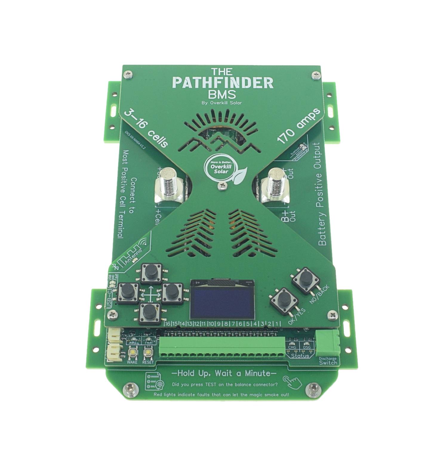
At the start of April I finished revising the main boards and decided to order a prototype instead of pushing the changes to a full run. Its a good thing too, because I have more changes to make. The predischarge circuit on the prototype is overheating when the system load is too high, and the load resistors were placed too close to the control circuits. I repositioned the load resistors away from the sensitive components, next to the FET temperature sensor, and added self resetting PTC fuses to prevent the predischarge circuit from melting down when the output has a short circuit. I also added a red “Overload” LED to give a clear indication that the load needs to be reduced.

The good news is under normal conditions predischarge is working GREAT. I have been testing with a big 48v inverter and without predischarge the BMS detects a short circuit from the inrush current. You can even hear the hard start noise, which is always a bit scary coming from “solid state” components. With predischarge enabled, the system starts up softly in about 1/2 second, with no stress. This is great because now we can leave the short circuit delay set at zero seconds for the fastest possible detection of actual short circuits, and have no issues with cold startup.

When the output has too much load or is actually shorted, the BMS will cancel the predischarge routine after an adjustable timeout, then retry after another adjustable delay. The output voltage target is also adjustable in terms of percent of battery voltage.

I have fixed the issues with the main board prototypes, and I am ready to order the full production run. The factory that makes them is on vacation the rest of the week, so I have all weekend to think about the changes.

BTW, so far we have not had to pay any new import taxes, so the presale price remains at $199. It looks like these parts actually fall under one of the exempted import codes for consumer electronics, so that’s nice.

Posted on 2 Comments

USB signal interference

I’ve been testing the pathfinder BMS with various equipment, and found that the USB connection is vulnerable to electrical noise from a big cheap inverter. We noticed this problem in the past with the JBD BMSs as well. (This doesn’t affect Wifi or Bluetooth)

This interference causes the USB port to stop communication, and the BMS must be rebooted to get it going again. We are working an getting the firmware to automatically restart the USB connection, but it doesn’t work yet. Remember, all Pathfinder BMSs can get firmware upgrades via OTA or UF2, so everyone will be able get the firmware solution later.

Other than getting a better inverter, the best solution seems to be adding ferrite chokes to the USB cable. I found that 2 or 3 snap on ferrite chokes is enough to stabilize the connection. Wrapping the cable 3 times thru a large ferrite ring had the best results, almost completely eliminating the interference when measured on the PC side.

Our very noisy inverter. This thing is crap, but great for testing interference.
Ferrites added to the USB cable. The large ring gave the best results.

We will do some experiments with adding common mode chokes to the Pathfinder circuit board and possibly add them to the next revision.

Better quality inverters produce far less noise, so this isn’t an issue for most customers. For example in the past we found that a Renogy inverter produced the least noise out all the units tested in our shop.

Details and scope traces:

I measured the signal interference using an oscilloscope at the PC end of the USB cable. Not much to see here. Yellow and Blue are the signal lines, Data+ and Data-.

The Inverter produces pulses of RF interference, and between pulses, the USB signal looks fine.

Inverter off, no chokes.
Inverter on, no chokes.

Here, I’ve zoomed out the time scale and added the purple trace on the inverter’s DC terminals. The pulses are happening at 21kHz, which is the inverter’s switching frequency. On the left side you can see a USB communication packet, which occurred between pulses of interference.

The real problem happens when the pulse of interference causes ringing on the USB signal lines as seen here. USB signals are mostly differential, but both lines pulled low means EOP or end-of-packet. This time, the ringing interference pulled the blue trace low enough that the USB controller would read an EOP signal.

Here, I added 3 snap on chokes (left), or wrapped the cable thru a large ferrite ring choke (right). In both cases the interference is dampened enough to prevent spurious EOP signals, but the large ring has the best results by far.

USB cable with 3 snap-on chokes, inverter on.
USB cable with Big ring choke, inverter on.

Posted on 4 Comments

New Self-Test feature

We added a super handy self-test feature to the Pathfinder terminal boards.

They now have a TEST button and fault indicator lights for each cell.

This feature will catch many of the wiring mistakes that can destroy the BMS before the damage can happen.

This test can detect swapped balance wires and open circuit cell connections, both of which would damage the voltage sensing inputs on the BMS main board if the terminal board was plugged in before fixing the faults.

The new 16 cell self-testing boards are finished and ready to ship with pre-orders.

(All of the terminal boards will have this feature at no extra cost)

Example Usage:

In this example, all of the balance wire connections are correct, and only the green LED lights when pressing the TEST button. This assembly is ready to connect to the BMS.


In this example, one of the cell terminal bus bars has been left off. Pressing the button lights up a single red LED corresponding to the open connection. If the BMS was plugged in like this, the full battery voltage would be present between 2 cell voltage inputs that are not tolerant of the full battery voltage.


In these examples, 2 balance wires are swapped out of position. The red LEDs will light even without pressing the test button. This may be the most damaging type of wiring fault because it puts negative voltage across several of the cell voltage inputs, which will destroy them if the connector is plugged into the BMS.


In this example, multiple faults are present and the red LEDs do a fun little dance. Might want to start over if it does this…

Posted on 2 Comments

First batch is sold out!

Sorry, I should have made this post 2 weeks ago: The first production run of Pathfinder BMSs is sold out!

Orders after order number 9025792 (from March 16) will ship from the SECOND production run of Pathfinder BMSs, so they will have some additional lead time beyond the original April 30 estimate.

Pre-order now to save your place in line!

The orders keep coming in, so the lead time will continue to increase for new orders until we get caught up. (Ramping up manufacturing is hard!)

Big thanks to everyone who has placed a pre-order, we really appreciate your support and patience.